A crane outrigger pad is a load-spreading element, not a piece of consumable matting. Specified correctly, it converts a high point load from the outrigger float into a pressure the ground can carry, and it does so without deflecting so much that contact is lost at the centre. Specified badly, the pad either sinks into the subgrade or bows under the float and transfers load through its edges only, which is the same as having no pad at all.
This guide is written for the engineer or buyer who has to put the pad line into a lift plan or a purchase order. It covers how to derive the load, why area and thickness do different jobs, what molecular weight actually buys you, and which tolerances and details cause trouble after delivery. Where a number appears it is a working range, not a guarantee; the final figure comes from the resin supplier’s data sheet and a ground bearing assessment for the specific site.
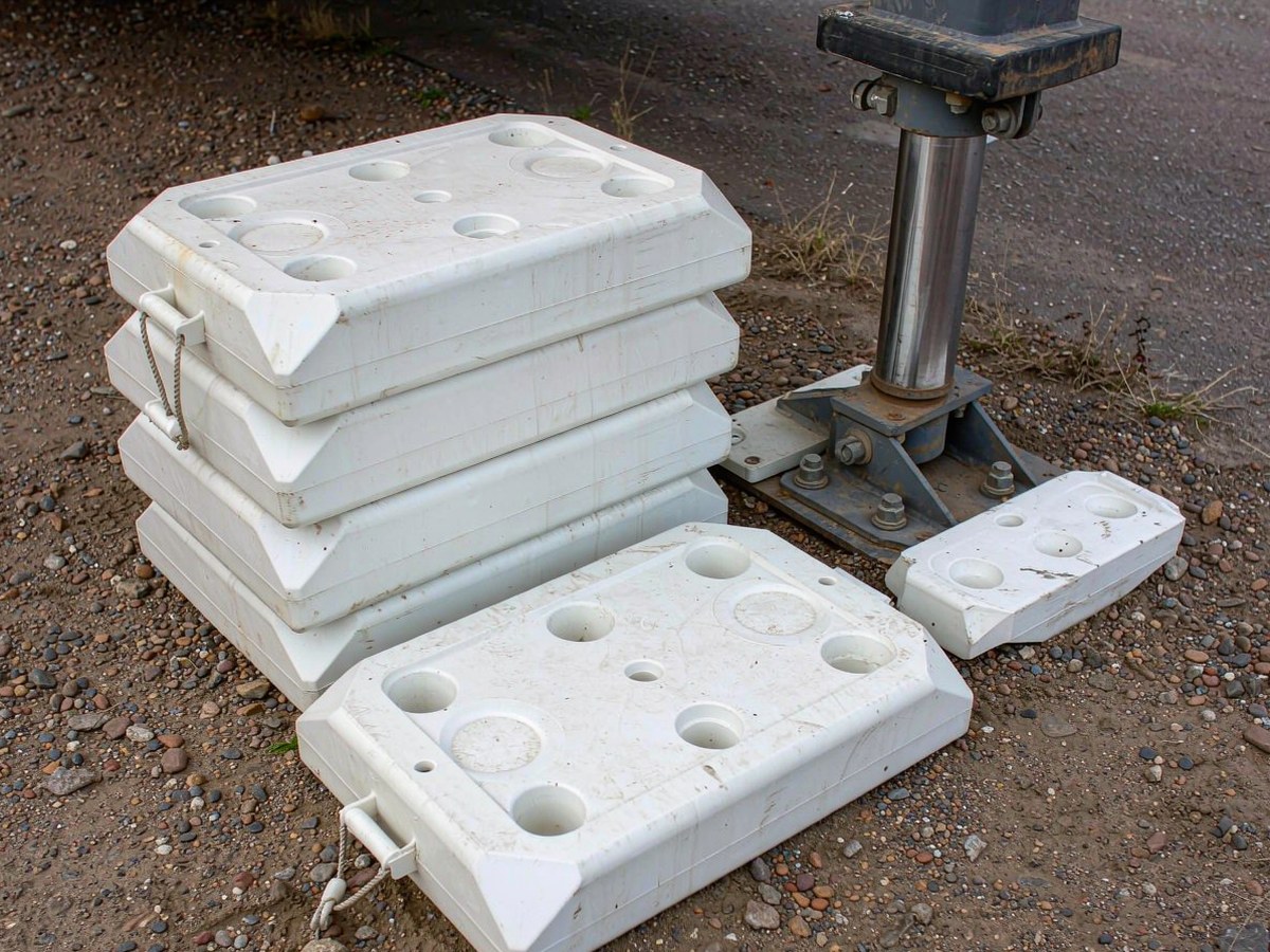
The most common specification error is sizing pads from the crane’s rated capacity. A 100 t crane does not put 25 t on each of four outriggers. The reaction at each float depends on boom configuration, radius, counterweight, wind, and which outrigger sits on the load side. Front-side floats routinely carry 60 to 80 percent of the total moment, and on a long boom at maximum radius a single float can see more than the nominal tonnage divided by two.
Take the maximum outrigger reaction from the manufacturer’s load chart for the actual lift configuration, then apply a dynamic factor. Breaking the load off the ground, swing acceleration and brake release all produce transient loads above the static chart value; a factor of 1.3 to 1.5 on the static reaction is normal practice, and higher where the load is picked from a truck bed or swung over the side. Only once that number is fixed does pad geometry mean anything.
Ground pressure is design load divided by effective contact area. That is the whole of the bearing calculation, and it is why footprint matters more than thickness on soft ground. If a float delivers 78 t to a 600 × 600 mm pad, nominal pressure is already about 21 t/m², before any allowance for a pad that only touches the ground around its perimeter.
That allowance matters. UHMWPE is a low modulus material; its compressive modulus sits well under 1 GPa, an order of magnitude below steel. A thin pad on an uneven surface deflects into a dish and makes contact over perhaps half to two thirds of its nominal area, so real ground pressure is 1.5 to 2 times the calculated figure. Thickness is what keeps the pad flat enough for the area you paid for to actually work. For crane outrigger pads, that distinction is the difference between a passing lift plan and a float that walks.
Thickness guidance only means something when it is tied to the subgrade. On a reinforced concrete slab or an engineered hardstanding, bearing capacity is rarely the constraint and 25 to 40 mm is enough for mobile plant and telehandlers; the pad is there to protect the surface and spread the float load, not to bridge a weak layer.
On compacted granular fill, the usual condition for a crane hardstand, 40 to 60 mm covers medium mobile cranes and 60 to 80 mm is the working range for all-terrain machines in the 100 to 250 t class. Where ground is soft, disturbed or recently backfilled, go to 80 to 120 mm and expect to stack two layers in a pyramid with the larger pad underneath. Layers in a stack should be the same material and the same size within a layer, and the float must sit centred with a clear margin on every side.
Two situations override any thickness table. First, point loading: if the float is a small spherical or conical foot, contact stress at the pad surface is high enough to cold form a permanent dish in a soft grade, and a steel spreader plate between float and pad costs less than another 40 mm of polymer. Second, duration: pads left under load for weeks creep. Reduce allowable stress, or increase thickness and area, when the crane will stand for more than a few days.
Crane outrigger pads are normally specified in the 3.5 to 6 million g/mol range, which is standard high viscosity UHMWPE. Higher molecular weight buys abrasion resistance and a little more creep resistance, but it also makes the sheet harder to consolidate, and a poorly sintered high molecular weight sheet with internal voids is worse than a well made standard grade. Molecular weight alone is not a quality claim.
What matters more is whether the sheet is virgin resin. Regrind and recycled UHMWPE are common in cheap pads and fail in a characteristic way: contamination particles and unmelted granules act as crack initiators, so the pad splits from an edge or a handle hole instead of deforming. The visible tell is speckling and a dull, uneven surface on a cut edge. Ask for the resin grade, the batch, and a written statement that no regrind is used.
State thickness tolerance explicitly, because it drives stack height and pad to pad contact. Plus or minus 1 mm on machined sheet, or plus or minus 2 percent on molded sheet, is normal. Anything wider turns a three layer stack into a rocking stack. Flatness matters just as much: a pad that is 3 mm out of flat will touch the layer below along one edge only.
Specify a chamfer on all edges, typically 20 to 25 mm at 45 degrees. A square cut UHMWPE edge is notch brittle. It chips on the first impact against asphalt or a steel float, and once a chip starts the crack runs. Chamfering also lets a pad ride over small steps instead of catching on them, and stops the corner digging into and cracking a concrete slab under load.
If anti-slip texture is needed, put it on the top face only. The bottom face should be flat so it beds onto the ground; a textured underside bridges on high points and reduces effective contact area. On wet or oily sites a shallow diamond or rib pattern on top is worth specifying, because dry friction between a steel float and UHMWPE is low by design and drops further with water or hydraulic oil present.
Weight is the first practical detail. At a density near 0.94 g/cm³, a 1200 × 1200 × 100 mm pad weighs roughly 135 kg. That is a two person lift at best and a manual handling problem in practice, so specify rope handles through molded or drilled holes, four stainless lifting eyes, or fork pockets on the larger sizes. Handle holes belong well away from the edge and generously radiused, because they are the most common origin of edge splits.
Do not bolt pads down hard. The linear expansion coefficient of UHMWPE is roughly 1.5 to 2.0 × 10⁻⁴ per K, so a 1200 mm pad moves about 6 mm across a 30 K swing between a cold night and a sunny afternoon. Clamped rigidly between steel, that movement either shears the fasteners or buckles the pad. Where pads are fixed to a frame, as on stabiliser legs or permanent hardstanding, use slotted holes and leave clearance.
Four failures account for most returns. Edge chipping and splitting start at square corners and handle holes. Permanent dishing under a concentrated float load comes from too thin a pad or too soft a grade. Creep settlement shows up as a pad that was flat on delivery and is noticeably thinner after a month under a parked crane. Sliding is the fourth: a low friction pad on a smooth wet slab lets the float walk under swing load, which is why top face texture and a recessed float seat are worth the extra cost.
A specification that gets the right pad is short and specific: design load per float including dynamic factor; required contact area from site ground capacity; thickness and tolerance; grade with molecular weight and confirmation of virgin resin; chamfer size; top face texture and bottom face flatness; handle or lifting eye arrangement; colour; and the documents required at delivery, meaning material certificate, batch traceability and compression stress data.
If you are working through a lift plan and need pad geometry, grade and fixing details matched to your crane class and ground conditions, send the outrigger reaction, the float footprint and the site ground capacity. That is enough to size the pad and confirm whether a single layer will do. Our crane outrigger pads are produced from virgin UHMWPE with chamfered edges, optional top face texture and rope or eye lifting points, and the same sheet specification carries over to crane stabilizer pads and ground protection mats where a continuous running surface is needed instead of discrete pads.