Most trough wear problems start at a corner. Drop a flat sheet into a U-shaped conveyor trough and you leave two longitudinal seams plus a void behind each bend, and that void is where fines pack, moisture sits and the liner slowly works loose. A U shape liner sheet solves that geometry problem directly: one continuous section, formed to the trough profile, with no joint anywhere in the material path.
What follows is for the engineer who has to specify one: the thickness callout, formed versus machined sections, where tolerances bite on site, and the failures that show up six months after commissioning.
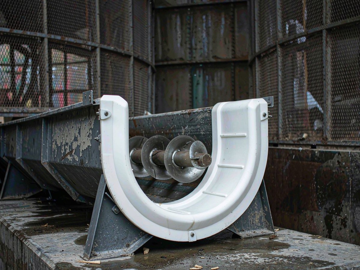
The obvious answer is a flat liner plus two corner pieces, but the real comparison is against the trough itself. In a screw conveyor casing, a belt loading zone or a small hopper discharge, the wear surface is a half-round or trapezoidal channel roughly 200 to 600 mm wide. Lining it with flat sheet means three pieces, two seams and two rows of fasteners standing in the flow.
A pre-formed section replaces that with a single drop-in part. The gains are practical: no seam for material to enter, no fasteners in the invert, and a radius that matches the trough instead of a hand-bent approximation. On screw conveyors the gain is larger, because a continuous liner keeps flight-to-casing clearance constant along the length, which is what actually controls carry-back and casing wear.
Be clear about where the part is wrong. On a transfer chute with a 3 m drop and lump sizes above 300 mm, a U profile is the wrong shape and the wrong thickness class; that duty belongs to impact-grade plate with a backing layer, as set out in our UHMWPE chute liner selection notes. The U section earns its place on troughs, screw casings, guide channels and small hoppers, not on high-energy impact zones.
There are three production routes and they behave differently in service. Hot forming brings a flat sheet to a temperature where it bends without grazing the surface, then shapes it over a mandrel and holds it until cool. Bend radius stays uniform, wall thickness is unchanged through the radius, and no stress is locked into the corner if the part is annealed afterwards.
Machining from block removes material instead of deforming it, so the section is the most dimensionally accurate of the three and can carry an asymmetric profile, a stepped flange or a drainage groove.
Welding flat pieces into a U is the route to avoid on anything carrying abrasive slurry or fine dry bulk. A welded corner is a stress raiser with different molecular orientation on each side, and in a vibrating trough the weld is the first place to crack. If a fabricator proposes welding because the section is “non-standard”, push back: a machined or formed part is almost always cheaper than a weld repair at month eight.
Suppliers quote double-layer sections as two figures, for example 3+9 or 4+12. The first is the wear layer, the second is the structural backing, and the total is what you measure with a caliper at goods-in. A 3+9 section is 12 mm overall and a 4+12 section is 16 mm. Buyers who read “3+9” as 9 mm routinely end up with a U shape liner sheet thinner than the casing clearance allows.
Pick between them from the wear allowance you can afford to lose, not from a generic recommendation. A trough handling dry grain or plastic pellets at moderate speed loses a millimetre or two a year, so a 3 mm wear layer is generous. A trough moving wet sand, clinker dust or mineral concentrate can consume that 3 mm in one season, which makes 4+12 the honest choice even when the price gap looks large at quotation stage.
Size the section so the backing is never exposed before the scheduled inspection interval. At annual inspection with 1.5 mm of wear per year, a 3 mm layer buys one comfortable cycle. At 4 mm a year the same section is a false economy and you will be changing it mid-cycle with the conveyor down.
Grade labels in this family are inconsistent across suppliers. PE300 and PE500 usually mean nominal molecular weight around three and five million g/mol, and our own U shape liner sheet range is offered at both. The label is shorthand, not a specification: two suppliers selling “PE500” may differ by a million in average molecular weight and by a wide margin in wear performance.
Put a measured number in the purchase order with a test method attached, either molecular weight with the method named, an intrinsic viscosity figure, or a specified wear test result. Do not accept a certificate that repeats the trade label with no value behind it.
Higher molecular weight is not free. Abrasion resistance and impact strength improve, but melt flow falls and the material becomes harder to form and to machine cleanly. For a formed U section the practical ceiling sits below the highest extrusion grades, because very high molecular weight sheet resists hot forming and springs back. Confirm the grade is one the supplier actually forms, not one they only sell as flat plate.
Double-layer sections come monochrome or bicolor, and the color option is routinely treated as cosmetic. It is not. In a bicolor build the wear layer is one color and the backing another, so a technician can see remaining thickness from the walkway without a gauge. When the second color appears across a defined area, the liner is due for replacement.
Write that trigger into the maintenance procedure while you are specifying. Replace when the contrasting color is visible over more than 20 percent of the invert width, or when it appears anywhere at the discharge lip. Without a written trigger, bicolor sheets run until the backing is through and the trough is scoring, which defeats the point of paying for the indicator.
The most common reason a section fails to install is not thickness. It is opening width, measured across the two free legs. A trough fabricated to plus or minus a few millimetres and a liner formed to nominal width can miss each other by enough that the part will not seat, and the field fix is usually to force it, which pre-loads the legs and invites cracking at the radius.
Specify the opening with a tolerance and specify how it is measured: across the outside of the legs, at the free edge, unrestrained at 23 degrees C. Do the same for leg height, flange width and inside radius. Then ask for the trough’s as-built dimensions rather than its drawing, because a welded trough that has run for years is rarely where the drawing says it is.
Where the match is marginal, an oversized leg trimmed on site is safer than an undersized one, so specify leg height with a plus tolerance and cut to fit. Drill fastener holes from a template at the works rather than marking through the liner in the field: drilling in place leaves swarf in the trough, and a burnt hole edge becomes a crack initiation point.
UHMWPE expands roughly 1.5 to 2.0 x 10^-4 per Kelvin, fifteen to twenty times the figure for steel. On flat sheet that is manageable: leave end gaps and slot the holes. A U section is harder because the geometry constrains itself. As the part warms the legs want to splay or the opening wants to close, depending on how the ends are held, and the resulting force lands on the fasteners and the radius.
Three measures handle it. Never fully restrain both ends of a long run: fix one end hard and let the other slide in slotted holes, with slot length calculated from length times expansion coefficient times the design temperature swing. Avoid over-clamping the legs flat to the casing, since a light pre-load is enough for a liner carrying no structural load. And if the casing runs hot, as at a dryer discharge or kiln feed point, confirm service temperature with the supplier before fixing thickness, because stiffness falls sharply near the softening region. Design to the metal temperature, not the ambient one: a casing under a hot process stream runs well above air temperature while the structure around it stays cool, and that differential is what loads the fasteners.
A fastener head standing in the flow is both a wear point and a snag point. On the invert, fasten through the flanges or the upper part of the legs, well above the material bed, and let the invert run free. Where a fastener must sit in the flow, use a countersunk head set flush or slightly below the surface, with a washer that spreads load over enough material to prevent pull-through.
Clamping is often better. A formed section can be held by its flanges between the casing wall and a retaining strip, which puts no holes in the wear surface and turns replacement into a ten-minute job instead of a shutdown. On screw conveyor casings this is the standard approach and is worth designing for even where the original casing was drilled.
If you bolt through, use wide washers or a continuous backing strip, and do not overtighten. UHMWPE creeps under sustained load, so a bolt tightened hard in summer is loose by winter, and one tightened to compensate dishes the sheet around the hole. Torque to seat the washer without dimpling, then re-check after the first month.
Failures are repetitive and mostly predictable. The signature shortens diagnosis and, more usefully, tells you which specification line to change next time.
The failure that is not on this list is wear of the invert in a correctly specified trough, because that is the liner doing its job. If an invert wears through in under a year on dry grain duty, the problem is the grade or the material, not the profile.
A request that produces comparable prices needs seven lines: casing as-built dimensions with tolerances on opening width, leg height and radius; total thickness expressed as wear layer plus backing; grade with a measured molecular weight or viscosity; color and whether bicolor is required; service temperature range; fixing method with hole pattern or a statement that the part is clamped only; and the inspection interval the wear allowance is sized against.
Add two more for unusual duty. State the bulk material, its moisture content and typical particle size, because wet fines and dry pellets wear a liner differently. State whether the casing vibrates, since that calls for the annealed forming route and a clamping detail that cannot fret.
Send dimensions as a sketch or measured drawing rather than a part number. Formed sections are made to the casing, not to a catalogue, and a supplier quoting from a number alone is quoting a guess. If you are unsure which thickness class fits your duty, send the trough width, the material and the throughput and ask for a recommendation with the wear allowance shown. That conversation is cheaper than a replacement order six months out. Our liner sheet specification page covers the flat-sheet equivalent for the rest of the run, and the two are normally ordered together.